
Universal Test Machine-Double Column Model
Model Number of YG(B)026GZ
[3rd Lab Qualification Certificate]:Tianfangbiao Certificate No.:TTTS-MCDT-FZ2507-05/TTTS-MCDT-FZ2305-05,TTTS-MCDT-FZ2304-05/TTTS-MCDT-FZ2529-03/TTTS-MCDT-FZ2530-02
[Patent number]:China Patent No.20986675
[Software Certificate]Software Certificate No.:11165679
[Calibration Certificate]:Shanghai Branch of the National Textile Metrology Station / Shanghai Textile Group Testing Standards Co., Ltd. Certificate No.:ZZ-2025031237
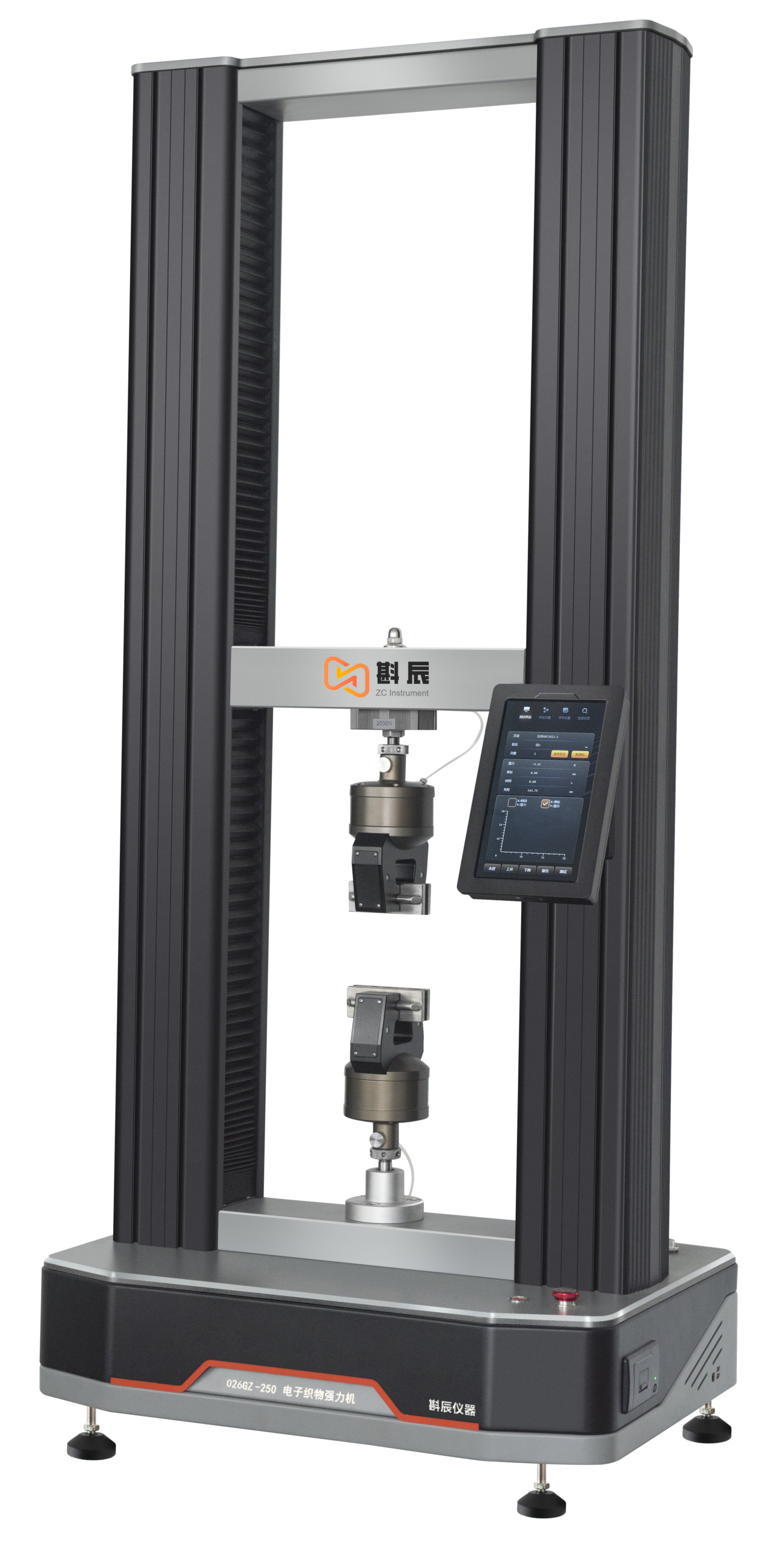
[Scope of Application]:
It is used for mechanical property testing—such as tensile, tear, burst, constant-elongation, constant-load, elasticity, seam slippage, and peel tests—on various textiles and related materials. It is also widely used for testing force values, elongation, and deformation in tensile, compression, bending, bonding, peel, tear, burst, and creep tests for rubber, plastics, leather, metals, wire/cable, paper, packaging, construction materials, petrochemicals, electrical components, and geotextiles.
[Relevant Standards]:
Determination of breaking force and elongation at break (strip method)-GBT | GB/T 3923.1-2013 |
Determination of breaking force and elongation at break (strip method)-ISO | ISO 13934-1:2013 |
Determination of breaking force and elongation at break (strip method)-AS | AS 2001.2.3.1:2001(R2016) |
Determination of breaking force and elongation at break (strip method)-ASTM D | ASTM D5035-2011(R2019), ASTMD6614-2007(2015) |
Determination of breaking force and elongation at break (strip method)-CAN/CGSB | CAN/CGSB-4.2NO.9.1-M90:R2013 |
Tensile properties – Determination of breaking force: Grab method-GBT | GB/T 3923.2-2013 |
Tensile properties – Determination of breaking force: Grab method-ISO | ISO 13934-2:2014 |
Tensile properties – Determination of breaking force: Grab method-AS | AS 2001.2.3.2-2001(R2016) |
Tensile properties – Determination of breaking force: Grab method-CAN/CGSB | CAN/CGSB-4.2NO.9.2-M90:R2013 |
Tensile properties – Determination of breaking force: Grab method-ASTM D | ASTM D5034-21 |
Tear Strength: Trouser-shaped tear method | GB/T 3917.2-2009 |
Tear strength: Trapezoidal tear | GB/T 3917.3-2009 |
Tear strength: Tongue tear | GB/T 3917.4:2009 |
Tear strength: Wing-shaped tear | GB/T 3917.5:2009 |
Tear Strength: Trouser-shaped tear method | ISO 13937-2:2000 |
Tear strength: Trapezoidal tear | ISO 9073-4-2021 |
Tear strength: Trapezoidal tear | ASTM D5587-2015 (R2019) |
Tear strength: Wing-shaped tear | ISO 13937-3:2000 |
Tear strength: Tongue tear | ISO 13937-4:2000 |
Tear strength of rubber- or plastics-coated fabrics | ISO 4674-1:2016; Method B |
Tear strength | ASTM D2261-2013(2017)e1 |
Tear strength | AS 2001.2.10:1986(R2016) |
Textiles — Determination of bursting strength — Steel ball method | GB/T 19976-2005 |
FZ/T 01030-2016 Method A | |
AS 2001.2.19:1988(R2016) | |
ASTM D3787-16(2020) | |
ASTM D6797-2015 | |
CAN/ CGSB-4.2 NO.11.2-M89:1989(R2013) | |
Knitted fabrics and elastic woven fabrics — Determination of seam strength and distension — Bursting method | FZ/T 01030-2016 Method B |
Test methods for elongation and recovery of wool textiles | FZ/T 70005-2006 |
Determination of the elasticity of fabrics – Part 1: Strip test method | EN 14704-1:2005 |
Determination of the elasticity of fabrics – Part 1: Strip test method | ISO 20932-1:2018/Amd.1:2021 |
Testing of Breaking Strength and Elongation of Coated Fabrics | ASTM D751-19 |
Textiles — Test method for tensile elasticity of woven fabrics | FZ/T 01034-2008 |
Determination of coating adhesion strength of coated fabrics | FZ/T 01010-2012 |
Test method for tensile elastic recovery of knitted fabrics | FZ/T 70006-2022 |
Determination of the resistance to yarn slippage in woven fabrics – Part 1: Fixed seam opening method | GB/T 13772.1-2008 |
ISO 13936-1:2004 | |
Determination of yarn slippage resistance in woven fabrics – Part 2: Fixed load method | GB/T 13772.2-2018 |
ISO 13936-2:2004 | |
Seam strength: Strip method | GB/T 13773.1-2008 |
ISO 13935-1:2014 | |
Seam strength: Grab method | GB/T 13773.2-2008 |
ISO 13935-2:2014 | |
Seam Slippage Strength & Breaking Strength | ASTM D1683/D1683M-2017(2018) |
Extensibility of seams in knitted garments | AATCC TS-015 |
Test method for seam slippage of wool-based fabrics | FZ/T 20019-2006 |
Knitted fabrics and elastic woven fabrics — Determination of seam strength and elongation — Grab method | FZ/T 01031-2016 |
Tensile Elasticity Test | Stretch and recovery LTD03,(FZ/T70006-20004,FZ/T01034-2008,FZ/T70005-2006) |
Standard test method for determining the yarn slippage resistance of woven fabrics at seams. | ASTM D434 |
Test method for seam strength of textile fabrics | JIS L1093 |
Test method for peel strength of fusible interlining | FZ/T 01085-2018 |
The standards listed above are representative examples; implementing some of the associated functions requires the additional purchase of specific grippers and the selection of appropriate sensors based on actual requirements.
[Instrument Features]:
1. Features automatic positioning after gripper replacement and automatic calibration of fixture positions; no manual calibration is required.
2. By limiting the closing air pressure and speed, the system automatically detects abnormal pneumatic fixture behavior, minimizes human error, and effectively reduces the risk of finger injuries caused by the fixture.
3. Traditional pneumatic grippers have fixed clamping forces during testing; insufficient force causes sample slippage, while excessive force damages the fabric. Our company’s proprietary incremental pressure technology allows the clamping force to increase dynamically alongside the sample’s tensile load, maintaining a balance that prevents both slippage and sample damage. (Optional feature)
4. TEDS sensor automatic recognition: the instrument automatically identifies the measurement range and applies software-based corrections after a sensor is replaced.
5. Comes pre-loaded with hundreds of programs and an extensive library of preset test methods, complying with major standards such as GB, FZ, AATCC, ASTM, ISO, JIS, EN, MS, and LTD.
6. The software system features fully proprietary copyright, facilitating future secondary development.
7. Designed with an electronic leveling system that visually displays the tilt angle, helping to minimize testing errors.
8. Supports full customization of standards, parameters, results, and reports.
9. Offers multiple test report formats (scatter plots, curves, raw data, etc.).
10. Includes robust support for calibration and verification tools.
11. Features IoT connectivity for real-time monitoring of the instrument’s operational status, faults, and other data.
12. Offers a choice of multiple measurement unit systems.
13. User-friendly interface design; immediately displays the instrument’s status and any fault alerts upon power-up.
14. Includes upper and lower travel limits for the crosshead, as well as protections against overload, over-voltage, over-current, overheating, under-voltage, and under-current. Features include automatic earth-leakage protection and manual emergency stop protection.
15. Equipped with a pneumatic chuck featuring interchangeable inserts; over 100 types of holders are available, with customization options based on customer materials.
16. Test data can be copied directly from the instrument via USB flash drive, facilitating testing across diverse locations and environments.
17. Optional barcode scanner and standard network communication module available.
18. Optional standard API interface available, supporting real-time data transmission with LIMS, automated workflows, and cross-system integration.
[Hardware Design]:
1. Robust, high-rigidity frame designed for a service life exceeding 30 years, featuring preloaded bearings and precision ball screws. Thickened crossheads and base beams, combined with low-tension drive belts, minimize stored energy during testing; this results in superior performance and more accurate modulus and strain measurements.
2. Excellent alignment and bending characteristics for precision guidance. Accurate stress and strain results during axial testing require a system with stable, rigid, and precise guides to ensure minimal lateral force impact on the specimen under load.
3. High-performance servo control drive system offering enhanced reliability. A high-power servo motor enables rapid acceleration at the start of tests and faster cycle times during cyclic testing. A dual-belt system synchronizes ball screw movement, eliminates crosshead tilting tendencies, and facilitates system alignment and precise positioning.
II. Embedded System-Based 7th Generation Digital Signal Processing (DSP) Control Technology
1. High-speed, low-vibration AC servo drive unit and high-resolution digital closed-loop controller.
2. Modular design featuring multi-channel data acquisition and analog output modules. Open data management architecture enables monitoring and control of load, deformation, displacement, speed, and more.
3. High-precision imported load cell utilizing a high-resolution 24-bit A/D converter; sampling frequency of 2000 Hz; maximum force resolution of 1:1,000,000 across the full range.
4. Equipped with a mobile touchscreen control box mounted on the frame; displays machine status and provides necessary controls for test execution, allowing most functional tests to be performed independently of a computer.
5. Dual-control capability between the main unit’s 10-inch HD touchscreen and a computer; includes precision fine-tuning switches to facilitate accurate adjustments to distance and timing, particularly after changing grips or fixtures for specialized requirements. 6. User-friendly open-type pneumatic grips: To ensure the material is clamped precisely along the vertical centerline, the open-type pneumatic grips allow the specimen to be fully inserted into the upper and lower gripping units. Manual adjustment ensures vertical alignment before clamping, thereby preventing jaw breakage or inaccurate force readings caused by improper clamping.
[Optional IoT Module Features]:
1. Device status statistics: Displays the current number of online and offline devices.
2. Device alarm display: Shows the number and severity levels of active alarms.
3. Real-time experiment data and progress display: Includes device status, current readings, experiment progress, and total duration.
4. Parameter configuration: Allows direct parameter settings to be sent to the instrument for modification, enabling bidirectional control between the instrument and the platform.
5. Map view: Displays the geographical location and status of various devices categorized by type.
6. Laboratory monitoring: Integrates surveillance cameras based on customer requirements to display real-time video feeds from the laboratory.
7. Customized unified management interface for laboratory equipment.
8. Temperature and humidity display: Integrates with third-party monitoring platforms to collect and display real-time environmental data from the laboratory.
9. Device monitoring and alarm notifications via mobile app and web interface.
10. Customizable app name and logo.
11. Multi-account platform management: Supports multi-level permission settings and account allocation across different devices, departments, and subsidiaries, facilitating unified enterprise management and enhancing data security.
12. Maintenance ticketing: Supports the submission of maintenance requests, allowing manufacturers to track and manage repairs.
13. Connectivity support: Supports Ethernet (wired), Wi-Fi, and Bluetooth for data exchange.
14. Simultaneous monitoring and management of multiple devices.
15. Large-capacity storage and analysis capabilities for test data.
16. Independent test data output for each workstation.
17. Full-system software OTA (Over-the-Air) update capability for continuous system evolution.
[Technical Specifications]:
1. Operating mode: Constant Rate of Extension (CRE) principle (internationally preferred);
Testing machine class: Class 0.5
2. Sampling frequency: 2000 readings/second
3. Force measurement range: 1%–100% of 2500N full scale
4. Force measurement system: Permissible errors (relative error of indicated value ≤ ±0.5%; repeatability error of indicated value ≤ 0.5%) and relative resolution meet the requirements for Class 0.5 testing machines.
5. Relative error of moving crosshead displacement indication: ≤ ±0.5%
6. Crosshead movement speed: 0.001 mm/min – 1000 mm/min (digital speed control); relative error of crosshead speed ≤ ±0.5%
7. Minimum scale interval: 0.01 N
8. Force measurement accuracy: ≤ ±0.2% F.S.
9. Tensile speed: 0.001 – 1000 mm/min (digital speed control); error ≤ ±1%
10. Gauge length (clamping distance): Digitally set, automatic positioning
11. Gauge length adjustment accuracy: ±0.1 mm
12. Clamping method: Manual clamping. Pneumatic clamping
13. Effective travel: 800mm; Gantry width: 420mm
14. Elongation resolution: 0.001mm
15. Power supply: AC 220V ±10%, 50Hz, 1kW
16. Dimensions: 540(L) × 510(W) × 1488(H) mm
17. Weight: 80kg (standard configuration)